In the modern digital economy, downtime is no longer just an inconvenience; it is a critical corporate liability. Every minute of a service outage translates directly to lost revenue, reputational damage, and, in many regulated industries, severe compliance penalties.
Many IT managers operate under the false assumption that hosting their infrastructure in a massive public cloud automatically guarantees 100% uptime. However, history is riddled with catastrophic regional outages—power grids fail, cooling systems break, and fiber optic trunks are severed by construction crews. If your entire architecture, even if highly clustered, sits within a single data center or a single geographic region, you have a Single Point of Failure (SPOF).
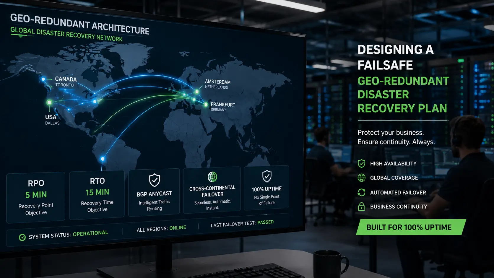
To achieve true 100% uptime, you must build resilience that transcends physical geography. You must engineer a Geo-Redundant Disaster Recovery (DR) Plan.
In this highly technical guide, we will explore how to architect cross-continental failover environments. We will define the critical metrics of disaster recovery, dissect the mechanics of active-passive and active-active environments, and demonstrate how strategically pairing North American and European bare metal servers can make your infrastructure practically indestructible.
Defining the Baseline: RPO and RTO
Before provisioning a single piece of hardware or writing a routing script, an IT architect must define the two most critical metrics of any disaster recovery plan: Recovery Point Objective (RPO) and Recovery Time Objective (RTO).
These two metrics dictate the entire technical design and financial budget of your failover architecture.
[Image illustrating the timeline difference between Recovery Point Objective (RPO) and Recovery Time Objective (RTO) in disaster recovery]
Recovery Point Objective (RPO)
RPO defines your organization's tolerance for data loss. It answers the question: "When a disaster strikes, how much data can we legally or operationally afford to lose?"
If you run a daily backup to an offsite server at midnight, and your primary server explodes at 11:59 PM, your RPO is 24 hours. You just lost an entire day of transactions.
For financial institutions, healthcare providers, and enterprise SaaS platforms, a 24-hour RPO is unacceptable. Their RPO must be zero. This requires real-time, continuous data replication across continents.
Recovery Time Objective (RTO)
RTO defines your organization's tolerance for downtime. It answers the question: "When a disaster strikes, how long can our application be offline before the business is critically damaged?"
If your DR plan requires an engineer to wake up, provision a new server, restore a database from a backup file, and manually update DNS records, your RTO is measured in hours.
To achieve 100% uptime, your RTO must be zero (or sub-second). This means the failover must be entirely automated, requiring no human intervention.
Achieving an RPO of zero and an RTO of zero requires a highly synchronized, multi-continent bare metal infrastructure.
Architecture Topologies: Active-Passive vs. Active-Active
To achieve geo-redundancy, you must establish at least two complete infrastructure environments separated by thousands of miles. How these two environments interact dictates your topology.
[Image comparing Active-Passive and Active-Active server architectures for disaster recovery failover]
The Active-Passive Failover Environment
In an Active-Passive setup, your primary site (e.g., a data center in New York) is "Active" and handles 100% of your production traffic. Your secondary site (e.g., a data center in London) is "Passive." It is a hot standby. The servers are powered on, the application is loaded, and the database is continuously receiving replicated data from the primary site, but it does not serve user traffic.
The Failover Trigger: A monitoring system (like a load balancer or a DNS health check) constantly pings the Active site. If the Active site stops responding, the routing layer automatically shifts all global traffic to the Passive site, promoting it to Active.
- Pros: Much easier to engineer. Database conflicts are avoided because only one database is ever written to at a time. It is highly cost-effective while still providing fantastic disaster recovery.
- Cons: During normal operations, you are paying for an entire secondary infrastructure footprint that is essentially sitting idle.
The Active-Active Failover Environment
In an Active-Active setup, both your primary and secondary sites handle production traffic simultaneously. Users in North America are routed to the US data center, while users in Europe are routed to the EU data center.
The Failover Trigger: If the US data center experiences a catastrophic fire, the routing layer simply stops sending traffic there and funnels 100% of the global traffic to the EU data center.
- Pros: Maximum hardware utilization. You get faster localized performance for global users, and the failover is truly instantaneous (zero RTO).
- Cons: Incredibly difficult to engineer at the database layer. Because both sites are actively writing data, you must implement complex multi-master database replication (like Galera Cluster or CockroachDB) across an ocean. If a network partition occurs, you risk a "split-brain" scenario where both databases write conflicting data.
The Network Magic: BGP Anycast and Cross-Connects
A geo-redundant architecture is useless if you cannot reliably route users to the surviving data center during a disaster. Traditional DNS failover is too slow; DNS records rely on TTL (Time to Live) caching, meaning some ISPs might cache the old IP address for hours, keeping a segment of your users offline.
To achieve an RTO of zero, enterprise architects rely on advanced network engineering.
Seamless Routing via BGP Anycast
BGP (Border Gateway Protocol) Anycast is the ultimate routing methodology for disaster recovery. Instead of giving your North American server one IP address and your European server a different IP address, BGP Anycast allows both data centers to broadcast the exact same IP address to the global internet.
When a user tries to access your application, internet routers look at the BGP tables and automatically route the user to the physically closest data center broadcasting that IP.
The DR Mechanism: If your North American data center goes offline, its BGP session drops. The global internet instantly updates its routing tables. Because the European data center is still broadcasting that same IP address, all North American traffic is automatically and seamlessly rerouted across the Atlantic. The user simply experiences a slight increase in latency, but the application remains online. There is no waiting for DNS caches to clear.
[Image demonstrating BGP Anycast routing global users to the nearest available data center]
Secure Synchronization via Cross-Connects
While BGP Anycast handles the public-facing frontend, your backend databases must synchronize data across continents. Doing this over the public internet introduces severe latency, jitter, and security vulnerabilities.
The solution is utilizing Cross-Connects to build a global private network. A cross-connect is a physical, dedicated Layer 2 fiber optic cable linking networks together. By leasing a private wavelength or utilizing an MPLS (Multiprotocol Label Switching) circuit between your two continental data centers, your primary and secondary databases communicate over a dedicated, unmetered, and private transatlantic pipe.
This guarantees consistent latency (typically ~70-90ms between New York and London), allowing for highly stable asynchronous database replication, ensuring an RPO of nearly zero.
The IPv6 Feature Advantage
When building these global private networks and establishing IPsec tunnels between continents, managing legacy IPv4 address space can become a routing nightmare of overlapping subnets and NAT (Network Address Translation) rules. Implementing IPv6 routing natively across your dedicated servers provides an astronomically large address space. This allows every single microservice, database node, and load balancer in both continents to possess a globally unique, routable IP address, vastly simplifying the configuration of your cross-continent VPN tunnels and cross-connect routes.
Strategic Continental Placement: Selecting Your Nodes
A geo-redundant architecture requires two distinct geographic pillars. Selecting the right locations ensures physical separation while optimizing transit paths. Here is how to pair North American and European bare metal servers for maximum resilience.
Node 1: The North American Anchor
Your primary or secondary node must sit in North America to capture the massive US consumer and enterprise markets.
- Option A: The USA dedicated server (New York or Dallas) Deploying in New York provides the absolute lowest latency for transatlantic database synchronization. Subsea fiber cables land near Long Island, meaning a New York server can communicate with Europe roughly 20-30 milliseconds faster than a server deep in the American Midwest. Alternatively, Dallas offers a centralized US routing hub, highly insulated from coastal natural disasters like hurricanes.
- Option B: The Canada dedicated server (Toronto or Montreal) For many IT managers, Canada is the ultimate North American DR location. Toronto and Montreal are on entirely different commercial power grids than the United States. If a massive, multi-state grid failure affects the US East Coast, Canadian data centers remain completely unaffected. Furthermore, PIPEDA (Canada’s privacy law) provides robust corporate data protections, making a Canadian node an excellent failover choice that still provides sub-20ms latency to New York and Chicago.
Node 2: The European Anchor
Your cross-continental node must sit in Western Europe to provide a physically isolated failsafe that is still highly connected to the rest of the world.
- Option A: The Amsterdam dedicated server (The European Gateway) Amsterdam is one of the most connected cities on Earth. It is home to the AMS-IX (Amsterdam Internet Exchange). Deploying your European DR node here guarantees massive, redundant fiber paths back to the United States. An Amsterdam node can comfortably absorb 100% of your global traffic during a US outage because the city's network infrastructure is designed to handle massive, multi-terabit loads effortlessly.
- Option B: The Frankfurt dedicated server (The Financial and Compliance Fortress) Frankfurt houses DE-CIX and is the financial capital of the Eurozone. If your application handles European financial data, GDPR dictates strict data sovereignty rules. An active-active architecture where European users hit a Frankfurt server and American users hit a US server ensures phenomenal localized performance. In the event of a total North American disaster, Frankfurt provides a legally unshakeable, highly secure bunker to keep your global operations running.
Putting It Together: A Step-by-Step Active-Passive Geo-DR Plan
To visualize how this works in practice, here is a blueprint for an enterprise-grade, active-passive disaster recovery architecture spanning the Atlantic:
- The Hardware Provisioning: Deploy a cluster of USA dedicated servers in New York (The Active Site). Deploy an identical cluster of Amsterdam dedicated servers (The Passive Site).
- The Network Layer: Acquire your own ASN (Autonomous System Number) and a /24 block of IP addresses. Announce this IP block via BGP Anycast from both New York and Amsterdam. Apply route weighting so global traffic prefers New York during normal operations.
- The Backend Synchronization: Establish a Layer 2 private Cross-Connect between New York and Amsterdam, leveraging the IPv6 feature set to avoid complex NAT configurations. Configure your primary PostgreSQL database in New York to stream continuous, asynchronous replication to the read-replica database in Amsterdam over this private tunnel.
- The Application Layer: Ensure the application code deployed in Amsterdam is identical to New York via CI/CD pipelines (e.g., using Ansible or Terraform).
- The Failover Execution: A massive power failure strikes New York. The New York routers go dark. BGP Anycast instantly withdraws the New York routes. Global traffic is automatically redirected to the Amsterdam IP broadcast. (RTO: < 5 seconds). A script on the Amsterdam database detects the loss of the primary master. It automatically promotes the Amsterdam read-replica database to a Master database. The Amsterdam application servers begin writing to the new Amsterdam master database. (RPO: The 70ms of data that was in transit over the Atlantic when the power failed).
Conclusion
Hoping a disaster never strikes is not an IT strategy. True enterprise resilience requires acknowledging that every individual data center is eventually susceptible to failure.
By designing a Failsafe Geo-Redundant Disaster Recovery Plan, you elevate your infrastructure from fragile to invincible. Understanding your exact RPO and RTO allows you to budget and engineer the right topology. By leveraging BGP Anycast and private cross-connects, you eliminate the delays of DNS caching and the vulnerabilities of the public internet.
Most importantly, by strategically anchoring your architecture across continents—pairing a USA dedicated server or Canada dedicated server with a robust Amsterdam dedicated server or Frankfurt dedicated server—you ensure that an entire hemisphere could go dark, and your business wouldn't miss a single transaction.
 Recent Topics for you